Simple Heterodyne detector and Frequency Division detector designs (4 different working designs and one concept versions of which I only built prototypes)
It seems the SA602/SA612/NE602/NE612 type mixers I uses in the heterodyne detectors become hard to find, be aware of fakes!
A while back I built heterodyne detectors with the kids at school. This was a lot of fun, but like with al starters projects we were missing a proper frequency readout.
I made some frequency counter using a project I found on the internet but is was quite complex to build, so I made myself a new circuitboard so all can be mounted as SMT parts in a modern factory. Most parts are mounted already, only a switch, two control wheels, some and wires for battery, microphones and speaker need to be soldered as wel as the tiny LED display.
The TeensyBat detector is quite complex "expensive" and more for the advanced user. I hope these simple heterodyne detectors can be the starters detector. Still quite useful but much quicker to build and less money involved.
(The performance however can not be compared to the TeensyBat detector. It is easy to miss a bat because of tuning to the wrong frequency where the Teensybat simply translates all bat sounds to audible frequencies)
Below you can see the new circuit board plans.
The design is based on the Batlistener IV by Laurens Wolfden
And the counter is based on "simpelest frequency meter with avr" by Danyk
The heterodyne tuning range is about 15-85kHz but effectiveness of the ultrasonic transducers is highest near their resonant frequencies of 25 and 40kHz
After the Heterodyne detector I also wanted something easier to use, no tuning and best chances to hear a bat so I built a Frequency Division detector with amplitude recovery.
The Heterodyne detector had some downsides, the frequency counter was slow, the display uses quite a bit of current, the multiplexing is a bit noisy and the tuning was not very linear. Also I wanted to include a MEMS microphone in stead of the transducers and a battery monitor would be nice. The downside of this design is the digital frequency generation in stead of the analog version earlier, the digital makes small steps (you probably do not notice this when tuning into short bat sounds).
Look at the Bat Listener Arduino at the bottom of the page for latest design.
The FD detector is something I sell on "Marktplaats" but you can also find it in the Parts section.
This image below, is not the final design of the first Heterodyne detector. I made some minor adjustments to lower unwanted digital signals, this is just to give you an idea of what it looks like. At the bottom of the page you can find a more recent design.
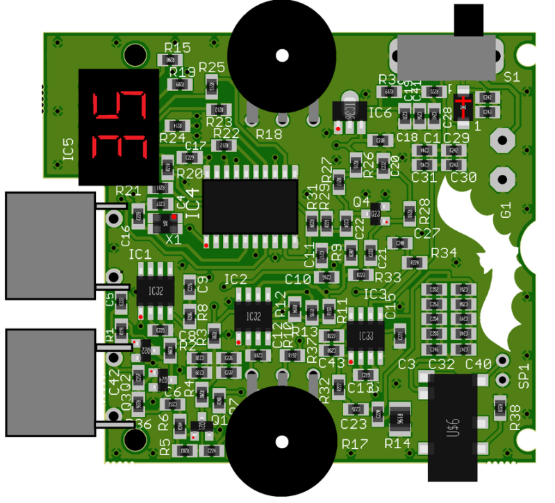
The enclosure is 103x63x26 which makes it a nice compact unit, on the new design we also have an extra ultrasonic transducer (for lower frequencies) the first ones only had 40kHz transducer and there also is a headphone connector. (The headpones connector probably is not in the most convenient place but as you can see the board gets a bit crowded.
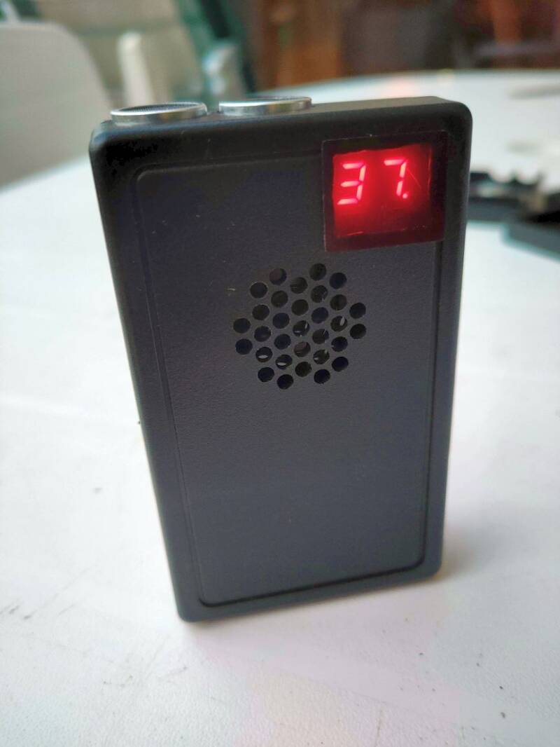

This is the heterodyne receiver part.

This is the frequency readout.

How to use.
This can be a very short manual.
Place a 9V battery in the battery compartment, please be aware the lid is tiny and it is not hard to damage. The small latch needs to be at the bottom.
Turn on the detector with the slide switch in the right.
Adjust the frequency with the left tuning wheel (the frequency is shown on the display, since the actual frequency is measured there is a little lag because time that is needed to measure.
Adjust the right wheel for the volume, if the volume is too loud you can experience feedback "whisteling sounds" from the speaker.
Battery Low, there is no low battery warning, so it might be wise to bring a fresh battery with you when you head outdoors. The detector however can work on a very low battery though.
There is a trick to know if the battery is full or low. Check the maximum frequency or your detector with a full battery. If this for example is 91kHz, it will be around 84kHz when the battery is low. (Not all detectors have the exact same range, so test and write down your low battery frequency)
Bouwbeschrijving (building manul, dutch only for now)
Single PCB files
These Gerber bom and cpl files are for ordering a single PCB, or multiple single PCB's
If you need more PCB and want to get them populated by the manufacturer, the 6-board panels are much more effective. I used JLC PCB, the quality is reasonable and they have good price for small numbers 5-10 pcs. Please note that I did not test this actual version of the PCB, please let me know if you find something that can be made better.
The following files are small panels of 6 boards
The 6-panel boards allow for better build price and lager numbers, for a 5 pcs (5x6 is a total of 30 boards) the price per board is much better
This is the Frequency division detector. (with amplitude recovery)
I do have some complete units for sale on the parts page.
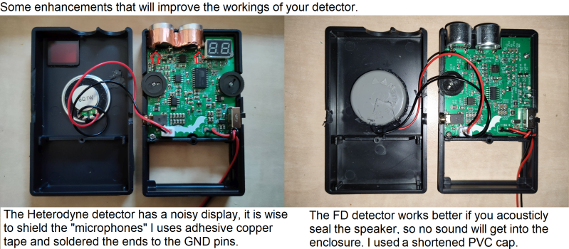
The FD detector uses a quad opamp, two as as microphone amplifier, one as schmitt trigger (to create dividable signals) and the fourth opamp of the IC is used as buffer for the rectified signal signal strength. The signal strength is than used in a CA3080 OTA, this is a variant of an opamp with special characteristics, there are not many replacements and many fakes on the market, be sure te get a real one. (I did buy some good ones from Amazon (seller eLifeeu) and Aliexpress (seller scsuho and seller cytx mall). I do have some spare IC's so mail me if you want one, I do not have these in the parts shop,
NEW Batlistener Arduino
I built a bunch of prototype boards, the design on the web-page has some issues fixed.
To make the a better version of the simple heterodyne that uses less current I wanted to change the an LCD display. I did however come across a beautiful tiny 0.42" OLED display. I expected this to be too small but with a 40 pixel high font is is very readable. The display also allows to show a battery monitor that tell us how full the battery is.
The Arduino is only used to generate the mixing frequency, display the chosen frequency and display the battery status. The rest still is analogue electronics, mixing is done with an SA602 and amplified wilt the trusted LM386.
There is some af-filtering on the output of the SA602 and LM386, the microphone amplifier is conditioned to amplify ultrasound and attenuate low frequencies. I used ADA4807 on my prototype but any other low voltage and low noise opamp should work just as well.
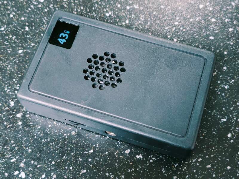
This is what it looks like, the display actually is white the display window is translucent black. The display is bright enough by night, in the daytime it looks quite dim with this "sunglass" window.
I used this style Arduino Pro Mini (8Mhz), only the red pads are used. 3.3V for the microphone and amplifier some from the Arduino VCC pin ,battery voltage input is on pin RAW
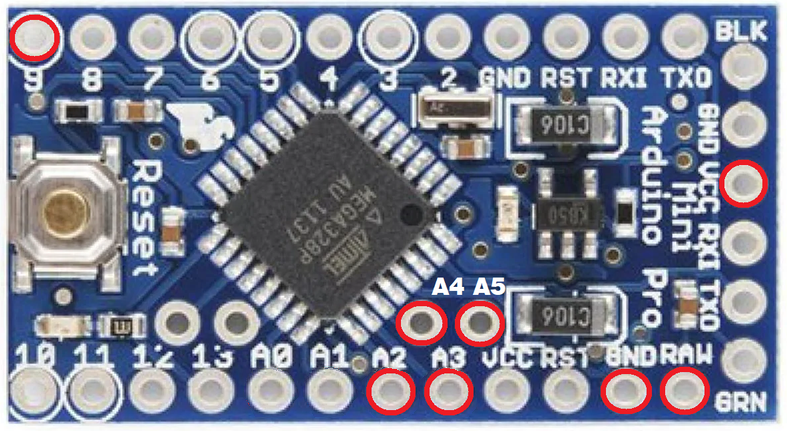
I used an Arduino Pro Micro on 8MHz to generate the frequency using the ToneAC library. The 20Mhz version can be used but that uses more current. The new design saves about 30% of energy. (18mA in standby)

This is what the PCB looks like.
It uses the same Knowles MEMS microphone as for the TeensyBat detector (SPU0410LR5H-QB on PCB)
The 8MHz Arduino pro-mini is mounted on te bottom side of the PCB. It is soldered close to the main-board, using 8 pins. An other small Arduino or ESP board can also be used but keep the wires short to prevent noise from the display-data. I did uses a fairly slow Arduino, as faster Arduino or ESP will use more current.
These (below) are the first boards of this series I built, the design that is on the website now has a few issues fixed, I do have the feeling I do hear some quiet humming in the headphones but not on the built in speaker, it seems the display data could be the source of the humming.

Update on okt. 25 because of a problem with the display footprint, Arduino pinout (3.3v output and analog pin offset)
Also added RC filtering on AF amp and Arduino power supply.
The R13/C20 construction to reduce high frequency amplification on the AF amplifier seems to introduce LF oscillation. The R13/C20 parts can be left out of the circuit.
If you did download the earlier files? please be aware of the 3.3v that seems to connect to the TDX (use an s-wire) and A3 A2 connections in stead of A0 and A1 connections as used in the ino. The new ino file already uses A2 and A3 for frequency adjust and battery monitor.
I noticed some humming in the headphones, somehow this seems to be noise made bu the display.
There is a way to lower this humming noise by using these lines in stead of the dim command, I tried the dim function to lower the power consumption but that does not make much difference.
You an comment out the dim line and add the lines below that, display dims quite a bit the hummig is almost cone using this bit of code.
//display.dim(true); //tried dim to save energy, does not make huge difference (1.4%)
display.ssd1306_command(SSD1306_SETPRECHARGE); //Precharge set to off (0x00) lowers the noise and dims the display.
display.ssd1306_command(0x00); //setting this to 0x00 does not lower the power consumption a lot (same as dim)
Ideas for new versions
As with every design there are always ideas for a better version.
The two verslons that that are drawn up here are not built yet so there could be some errors, there are no images or gerbers to release as the functionally is not checked.
The Arduino based heterodyne bat detector with MEMS microphone element gets a stereo brother.
This version as an extra microphone, mixed IC and stereo amplifier. The stereo effect helps to find the direction the sound comes from, This only works on the headset, if the headset is not used, the speaker only lets you hear the left channel. Is the headphones are connected no sound comes from the speaker. The volume on the headset is not limited as in the earlier(mono) version so be careful with adjusting volume.
The frequency divider detector get a wide-band microphone.
The earlier version used ultrasonic transducers (UST) that allows to detect the most common species. The big benefit of using UST's is their immunity for low frequency sounds, they only pick up sounds near the resonant frequency. This alo ment a soprano pip or horseshoe could be missed as also higher ultrasound frequencies were not picked-up by the UST's
Using a Knowles MEMS element helps to hear all sounds, some filtering in the amplifier circuit is added to keep the low frequencies out of the system. It seems the acoustic shielding for the speaker as used in the UST revision is not necessary.
Stereo version Heterodyne (Zoogdierendag 2025)
Dit toestel is inmiddels gebouwd tijdens de zoogdierendag 2025
Stereo heterodyne uses oled heterodyne software.


